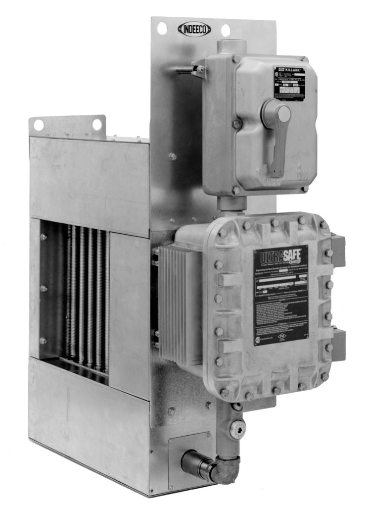
Ultra-Safe™ Explosion-proof Duct Heaters
Indeeco’s Ultra-Safe Explosion-Proof Duct Heaters are engineered for use in hazardous environments where explosive gases or dusts are present. These heaters are cCSAus approved for virtually all Class I and Class II, Division 1 and 2 applications, making them a trusted choice across industries requiring the highest safety standards.
With ignition temperatures as low as 320°F (160°C) and six standard sizes designed to fit a wide range of ducts, these heaters deliver powerful, flexible solutions for industrial air heating. Available with power ratings up to 240 kW and voltages up to 600V, they are ideal for both standard and custom duct heating systems.
- cCSAus Approved for Class I & II, Division 1 & 2 hazardous locations
- Low Ignition Temperatures—as low as 320°F (160°C) for enhanced safety
- Six Standard Sizes to fit most commercial and industrial duct systems
- High Output Ratings—up to 240 kW and 600 volts
- Custom Options available to meet specific airflow or control requirements
- Built for long-term reliability in extreme environments
Approvals
Standard Construction
Heat Exchanger has copper tubes with integral aluminum fins. Each unit undergoes hydrostatic testing at 350 psig, five times the pressure relief valve setting of 70 psig.
Heat Transfer Fluid is propylene glycol, a non-toxic, rust-inhibiting fluid that provides freeze protection to –49°F (–45°C). Its high heat transfer rate at 70 psig makes the heat exchanger suitable for gases that ignite at temperatures as low as 320°F (160°C). Thus every Ultra-Safe heater is rated for Temperature Code T3C.
Industrial Grade Heating Elements, built by Indeeco, are .475” (1.21 cm) diameter to provide extra insulation between the coil and sheath for high voltage protection.
Frame is heavy gauge galvanized steel, fitted with lifting lugs to facilitate installation.
Four Levels of Safety are provided on every heater: automatic and manual reset thermal cutouts, airflow interlock, and pressure relief valve.
Two thermal cutouts limit the heat transfer fluid temperature, assuring thermal safety. The automatic reset operates a “primary” magnetic contactor. The manual reset operates a separate backup magnetic contactor. If either cutout opens, the entire heater is de-energized.
A fan relay, acting as an airflow interlock, prevents the heater from being energized unless the fan starter is on.
The pressure relief valve on the heat exchanger opens only if the thermal cutout system fails to prevent excessive temperatures.
Standard Built-in Control Package includes the following components mounted in a cast aluminum explosion-proof enclosure:
- De-energizing control and back-up magnetic contactors.
- 24V control circuit transformer.
- Fan relay, supplied with 24V or 120V holding coil to match the fan starter coil voltage.
- Terminal blocks for field power and control wiring.
- Grounding terminal.
- Supplemental fusing for heaters drawing more than 48 amps.
Installation
Complete installation instructions are furnished with each heater. Following are some guidelines:
The heater must be securely attached to external duct flanges.
The heater must be adequately supported. If the duct flanges will not afford enough support, overhead hangers attached to the lifting lugs may be used for additional support.
Each heater is suitable for a variety of duct sizes. See Table XIX on page 48 for maximum and minimum dimensions. Note that duct height and width can vary independently.
Airflow must be horizontal. See page 44 for airflow requirements.
Temperature Control
Solid-State SCR Control
When temperature must be controlled precisely, or for larger KW heaters, built-in SCR’s manufactured by Indeeco are recommended. They are furnished with field-selected inputs of 2200 or 135 ohms, 0-10 VDC, or 4-20 mA. SCR’s have zero-cross firing to eliminate radio frequency interference.
To meet FM and CSA requirements, multi-unit designs (up to four heating units in series) also have controls set at 80°F (27°C) to limit the inlet air temperature to all but the inlet unit. These limit controls prevent excessive temperatures at the heater outlet as the inlet air temperature rises.
Single Stage Control
For many lower KW applications, single stage on/off control is adequate. For higher KW ratings, solid-state SCR control is recommended.
Custom Options
Corrosion Resistant Construction
Stainless frame, coated heat exchanger, epoxy-coated NEMA 4X, 7, 9 terminal box, conduit and fittings.
Built-On Disconnect Switch
To meet NEC requirement for a disconnect at or within sight of the heater. (Not available for outdoor, washdown, Group B, or 60 amps or greater)
Built-on Airflow Switch
An explosion-proof differential pressure switch replaces the fan relay. Use only for positive pressure inside the duct. (Not available for outdoor, washdown or Group B).
Supplementary Fusing
For heaters drawing 48 amps or less. Fusing is standard above 48 amps.
“Warning” Pilot Light
Red light to indicate when a thermal cutout or airflow interlock has tripped.
“Heater On” Pilot Light
Green light indicates when there is power to the heater.
Disconnecting Magnetic Contactors
Contactors that break all ungrounded lines replace standard de-energizing contactors.
120 Volt Control Circuit
A 120V control transformer with both primary legs fused replaces the standard 24V transformer. (Not available with solid-state SCR control.)
NEMA 4
Construction
Explosion-proof box is gasketed for outdoor or wet locations.
Group B Construction
For Class I, Group B areas. Heater will be rated for Classes I and II; Divisions 1 and 2; Groups B, C, D, E, F and G.
Classifications
- Classes I and II, Division 1 and 2
- Groups B, C, D, F and G
- Temperature Code T3C, 320°F (160°C)