Explosion-Proof Flanged Immersion Heaters
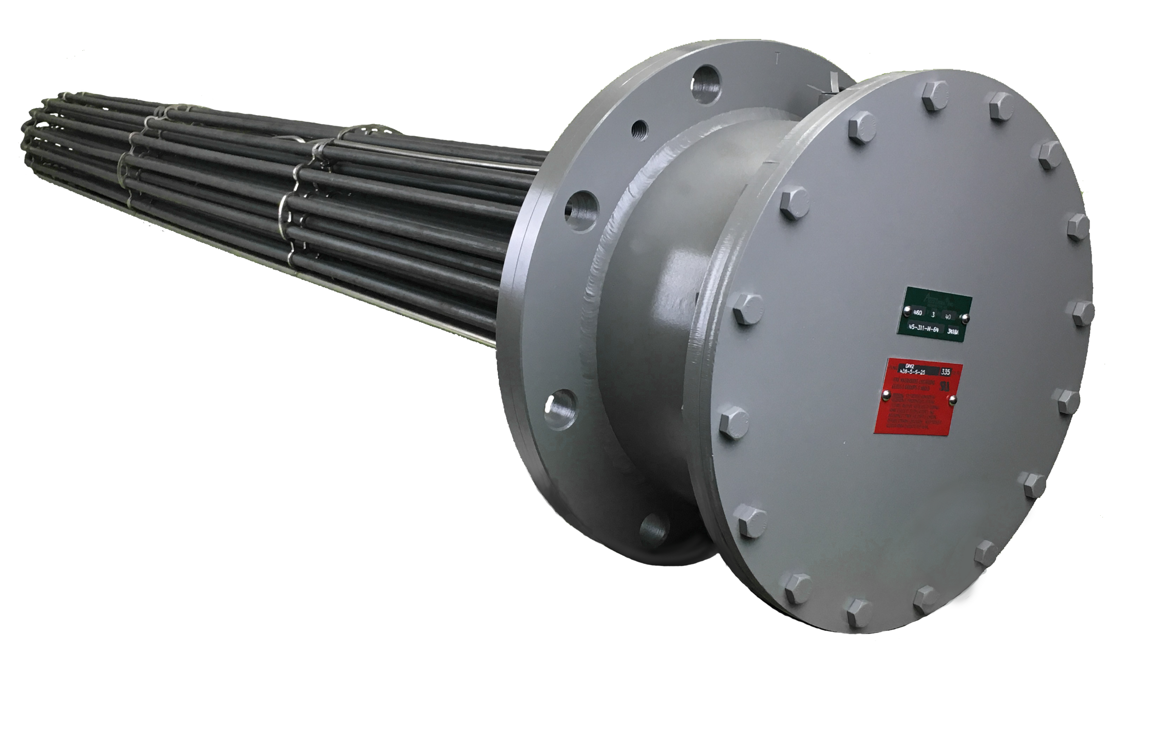
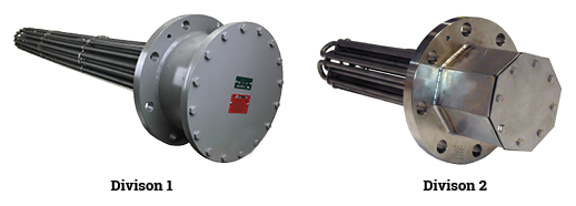
Indeeco’s explosion-proof flanged immersion heaters are one of the most widely used solutions for heating fluids and gases in hazardous locations. CSA approved for Class 1, Division 1, Group B, C and D locations and/or approved for ATEX, UKCA and IECEx Zone 1 and/or Zone 21 locations. Indeeco’s explosion-proof flange heaters are designed for use in tanks, vessels, and in-line heating.
Approvals


Standard Features
Wattages up to 8.5 megawatts
Watt densities up to 200 w/in2
Voltages up to 600V
Element sheath temperatures up to 1,500°F
Multiple flange and element materials
Flange sizes up to 30″ and class 2500 ASME B16.5
ANSI B16.5 class 150 or class 300 flange 3″ up to 30″ (max flange size of 24″ for div 1 applications)
Designed to fit into schedule 40 or schedule STD pipe for the given flange size
Flange material A105 carbon stl, A182 304/304L or 316/316L stainless steel
Elements sheath materials available; steel, 304 SST, 316 SST, 321 SST, incoloy 800, incoloy 840, copper
Epoxy or RTV sealed heating elements to prevent moisture absorption
Stainless steel welded bussing to eliminate loose connections
Heater circuits divided into 48A max as default
Heavy duty, low pressure drop design, 304 SST element support spacers provided on 24″ centers
Spacer support rods provided for immersed length greater than 30″
Lifting lugs for heaters 4″ and larger
Nitrile bonded fiber, or SST/graphite spiral flange gasket provided as standard
Optional Features
Extended terminal box
Provided when necessary to allow for cooler operation of the terminal box. This allows the heating elements to be sealed with epoxy or RTV and for the customer to provide incoming wire with a much lower insulation temperature rating.
ASME
The heater can be supplied in accordance with ASME section VIII Div. 1 U-Part stamped and certified.
PED
The heater can be supplied with materials and welding
procedures in compliance with the European Pressure
Equipment Directive (2014/68/EU).
NACE
The heater can be supplied with materials, welds and their heat
affected zones with hardness testing values in compliance with
ANSI / NACE MR0175/ISO15156
Thermostats
Bulb and capillary pilot duty or load carrying thermostats can be provided to control the heater. The thermostat bulb can be installed in a thermowell to sense process or element sheath temperature.
Thermocouples
Type J or K thermocouples can be provided to monitor the process or element sheath temperatures. Thermocouples provided with a ceramic wafer head and screw terminals for ease of wiring. Alternate type E or T available.
Hermetically sealed element terminations
A ceramic to metal soldered seal can be provided to eliminate the possibility of moisture from entering the heating element.
Removable bussing
Allows troubleshooting and isolation of a failed heating element.
Cross-baffle
Construction utilizes alternating half baffles spaced closely to cause increased flow velocity across the heating elements to allow better heat transfer from the elements to the fluid.
Add support rods for flanges with length less than 30″
Support rods can be added to shorter heater with high flow to keep the element support spacers in place.
Larger heater circuits for greater than 48A per circuit
Heavy wall pipe design
Element bundles with smaller outside diameter can be provided for any flange size requested.
Pickle and Passivate
A chemical treatment in nitric acid can be performed to remove free iron from the outer surface of stainless steel for applications sensitive to contaminants.
Electro-polish
Is a process similar to plating using cathode and anode reactions but material is removed rather than added to the heater surfaces in order to provide a clean and bright finish.
Ring and cover weatherproof or corrosion resistant enclosures
Heavy duty pipe and plate construction.
Other element sheath and flange materials available
Flange ratings greater than class 300 are available up to class 2500
Classifications
Class I, Division 2, Groups A, B, C and D
Class I, Division 1, Groups B, C and D
Class II, Division 1, Groups E, F and G
UL STD 50, Type 4 or 4X
II 2 G D
Ex db IIB+H2 Tx or Txxx°C Gb
Ex tb IIIC Txxx°C TL xxx°C Db IP66


