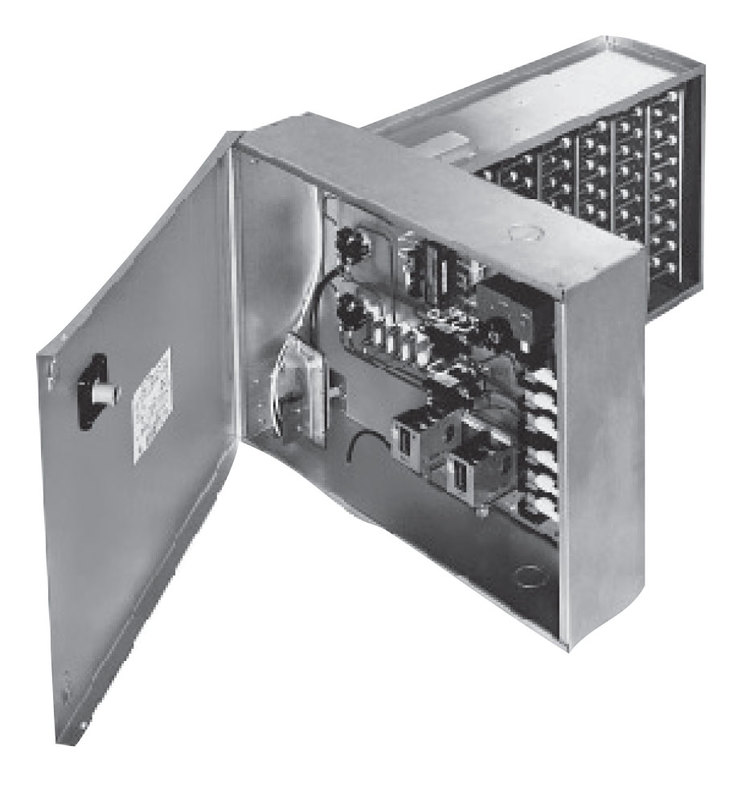
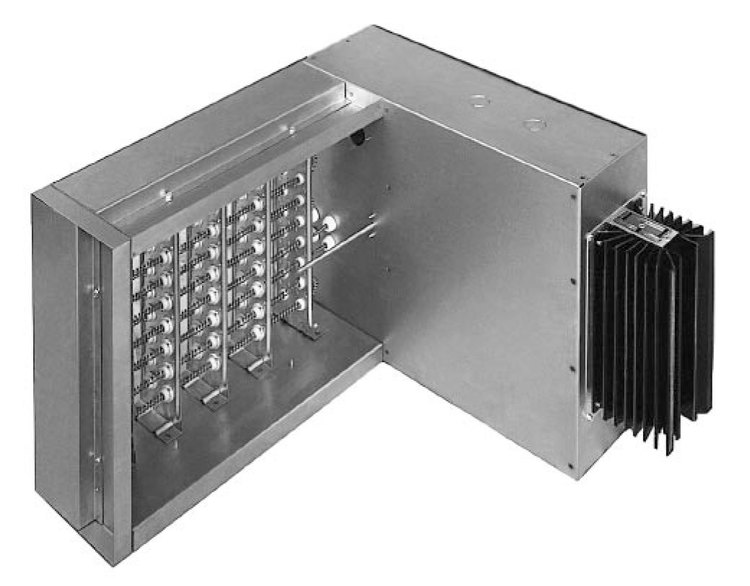
QUA & QUZ Standard Open Coil Duct Heaters
Indeeco’s QUA and QUZ heater lines are engineered to meet the vast majority of typical space heating applications, offering a balance of performance, flexibility, and ease of ordering. With models available up to 456 kW, these heaters are ideal for both light and heavy industrial environments.
To streamline project timelines, Indeeco offers both standard and quick ship programs, ensuring fast delivery across the full QUA and QUZ product range. Whether you need a high-performance solution for new construction or a rapid replacement for an existing system, these heaters are ready to meet the demand.
Approvals
Standard Features
KW Ratings
QUA and QUZ heaters are available up to 456 KW. The KW ratings are limited both by frame size and electrical characteristics. Heater availability can be determined by contacting an INDEECO representative, who can provide a computerized heater selection with exact heater dimensions in minutes.
Frame Sizes
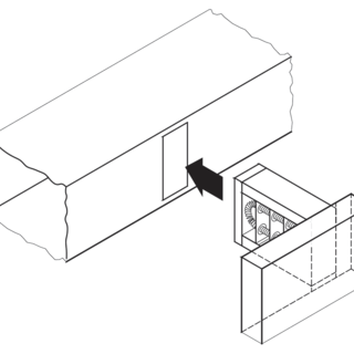
The use of a standard open coil QUA slip-in heater will both reduce cost and permit rapid shipment. QUA frame sizes range from the smallest at 8″ wide by 6″ high to the largest 48″ wide by 40″ high or 72″ wide by 30″ high. The QUA offering has been opened up to allow for any duct size in between these sizes and includes fractional widths and heights dimensions (i.e. 24.625″ by 17.25″). INDEECO can manufacture a custom slip-in frame size if your requirements exceed the QUA offering.
All QUA heaters may be installed in ducts with up to 1″ of interior lining, but the heater must be selected to fit the inside duct dimensions. For example, to fit a duct with 36″ x 16″ outside dimensions, but with 1″ of interior insulation, specify a 35″ x 14″ heater.
QUZ flanged open coil heater frame sizes range from the smallest at 8″ wide by 6″ high to the largest at 48″ wide by 38″ high or 72″ wide by 28″ high or any duct size in between these sizes (i.e. 35.75″ by 27.75″). QUZ cannot be used with interior lines ducts. If you require a frame size not offered by the QUZ then Indeeco can manufacture a custom frame size to meet virtually any application.
Detail Dimensions
The wide variety of QUA and QUZ heaters makes it impractical to list the exact heater dimensions for every possible heater. For dimensional details, contact your local INDEECO representative.
Voltage and Phase
Heaters are available in a variety of voltage and phase combinations. All are for operation at 50 or 60 Hz. When three-phase is specified, each heating stage will be furnished with a multiple of three elements to give a balanced three-phase load.
Control Circuit Options & Special Features
QUA and QUZ heaters are available with a variety of Control Options and a full range of Special Features.
Number of Heating Stages
Single and three-phase QUA and QUZ heaters are available with multiple heating stages. To comply with our UL and NEC maximum circuit sizes, no stage is rated at more than 48 amps.
Special Features
Horizontal Airflow
Allows heater to be used in applications where airflow is either right or left.
Vertical Airflow
Allows heater to be used in applications where airflow is either vertical up (U3) or vertical down (U5.)
Pressure Plate
40% open perforated plate installed onto the inlet side of the heater frame to help even out irregular airflow patterns.
Protective Screen
Wire mesh screen for attachment to the heater frame. Can be furnished for one or both sides.
Stainless Steel Frame and Terminal Box
Heater frame and terminal box constructed of 304 stainless steel.
Aluminized Steel Frame and Terminal Box
Heater frame and terminal box constructed of aluminized steel.
Insulated Duct Construction for Slip-in Heaters
Used in ducts lined with more than 1″ thick interior insulation. Inside duct dimensions and insulation thickness must be specified. Maximum 6″ thick lining.
Unheated Sections
Extended terminal pins to provide an unheated section adjacent to the heater terminal box. Maximum extended terminal pin length of 6″.
Substitute Negative Pressure Switch
Allows heater to be used on inlet side of fan.
Right/Down Terminal Box Overhang
Heater will be supplied with terminal box overhang on right (if horizontal airflow installation) or downward (if vertical airflow installation).
Insulated Terminal Box
Prevents condensation inside terminal box when heater is installed in air conditioning duct running through un-airconditioned area.
Dust-Tight Terminal Box
Allows installation in dusty areas and satisfies local codes requiring dust-tight box, if installed in area used as return air plenum.
Remote Panelboard
All controls except thermal cutouts, airflow switch and pilot switch will be supplied in a separate NEMA 1 panelboard.
Add “Stage On” Pilot Light(s)
To indicate when each heating stage is producing heat.
Add “Low Airflow” and “Heater On” Pilot Lights
Separate pilot lights to indicate that power has been supplied to the heater, that it is ready for operation, and whether airflow has been interrupted.
Fan Relay
When static pressure in the duct is too low (below .07″ WC) to operate the airflow switch or when airflow switch is not desired. (000) denotes holding coil 24, 120, 208, 240, or 277 volts.
Add Indeeco Electronic Step Controller
Allows better temperature control of high capacity heater by using multiple stages controlled by electronic thermostat and step controller.
Low Watt Density Coils
To meet specifications which call for low watt density coils.
Add Built-in PE Transducer
To allow for pneumatic control.
Transformer Primary Fusing
Add transformer primary fusing.
Delete Transformer
Allows control circuit to be obtained from source outside the heater or, when line voltage is equal to control voltage, directly from power lines within the heater.
Delete Transformer & Contactors
Allows for control of heater directly using load carrying thermostats.
Transformer Secondary Fusing
External fused and grounded transformer secondary for Class II 24 volt control circuits.
Additional User Control Circuit Voltage
Heater control circuit transformer sized for additional user VA. A control terminal block is furnished for field connection.
Delete Disconnect
Allows for use of field installed disconnecting means. (Must be within sight of the heater.)
Fused Disconnect Switch
Door interlocking disconnect with line fusing for heaters loads up to 48 amps or less.
Linear Limit Automatic Reset Thermal Cutout
Automatic reset linear limit thermal cutout wired in series with the disc type automatic reset to provide redundant primary over temperature protection.
Add Fuses for Heaters Rated 48 Amps or Less
Allows for addition of one set of fuses to low amperage heaters that do not need internal fusing to meet UL and NEC requirements


