Electric Heating Elements
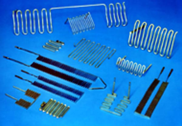
Electric heating elements in the form of coil, ribbon or rod (Fig. 1) made from alloys such as nickel-chromium, iron-chromium-aluminum and refractory metals are widely used throughout the heat-treating industry. They are found in both low- and high-temperature furnaces and perform well in cyclic-duty service. Let’s learn more.
The temperature of a heating element and its surroundings is primarily dependent on the rate at which energy is being supplied and the rate at which it is able to transfer this energy – in the form of heat – to its surroundings. There is a critical rate of heat exchange, reflected in a design value called the watt-density, measured in watts/in2. Ideally, the power being generated is only slightly greater than the heat-transfer rate demanded by the load. A good match means that the elements will not run too hot, will heat the load in a reasonable amount of time and will not fail prematurely. Good element life and good temperature uniformity within the workload area are the result. The elements themselves can be supported from the furnace sidewalls, suspended from the roof or laid on the furnace floor. Refractory, alloy or ceramic hooks, hangers and supports are commonplace as is placing the elements into ceramic “form” tile.
The type of alloy used depends on the furnace temperature rating (Table 1) and the type of atmosphere used (Table 2). The factors that influence the life of a metallic heating element include the type of furnace atmosphere, watt density, operating temperature, type of service (continuous or intermittent) and maintenance. Furnace type, design and loading play an important role as well.
By contrast, many ovens use sheathed heaters in which the heating coil is enclosed in a metallic sheath that is packed with a magnesium oxide (MgO) insulating material. These tubular heaters are offered with a choice of sheath materials for different temperatures and environments, including steel, copper-coated steel, Incoloy®, Inconel® and stainless steel.
Tips for Extended Service Life
To maximize element life, be sure to do the following:
- Understand that for every 1% increase in voltage, the result will be a 2% increase in power. This is especially important since most power utilities in the U.S. can fluctuate as much as ±10% of nominal voltage. If purchasing a new electric furnace, be sure to accurately measure your plant voltage, and convey this to the OEM to have them design accordingly.
- Know the design limitation (watt density) of the heating elements. If accurate wattage is important, test the finished element design to determine the proper allowance for rise in resistance with temperature.
- If more power is needed, increase the diameter of the element wire or reduce the length of the element.
- Leave adequate room for expansion and contraction. If an element must be anchored between terminals, monitor it to ensure that excess warpage or creep (movement under its own weight over time) will not adversely affect the operation of the element or equipment.
- Understand the cyclic nature of your application. Elements need adequate space to move on their hangers or supports. Do not locate elements so close to the bottom of a furnace or to a refractory shelf that expansion will cause them to rest on the refractory, potentially creating an area where heat will not dissipate from the element, allowing a hot spot to develop.
- Install carefully. Check that the terminal holes through the insulation are in alignment so that the elements slide in without striking the opposite side or are put under tension due to forcing them into position. Be sure to center the elements in the furnace chamber so that no portion of the heating section of the element is in the brickwork.
- Design for the proper element voltage. Do not run an element designed for 230 volts on a 460-volt supply.
- Keep all types of contaminants and foreign substances away from the elements, including sulfur-based compounds (these form low-melting eutectics with the nickel in the heating element and result in premature element failure), phosphorous or oil. Avoid contaminants such as excess cleaning compounds that may build up on the surface of an element over time, creating an insulating layer. If melting has occurred inside a ceramic support plate or form tile, replace it.
- Welded joints between element sections are best. Pressed or pressure joints can be used but must be thoroughly tested.
- Be sure that the elements are properly secured to the terminals, and periodically check that the connections remain tight (this must be done with the power off).
Read the rest here.